


|
|
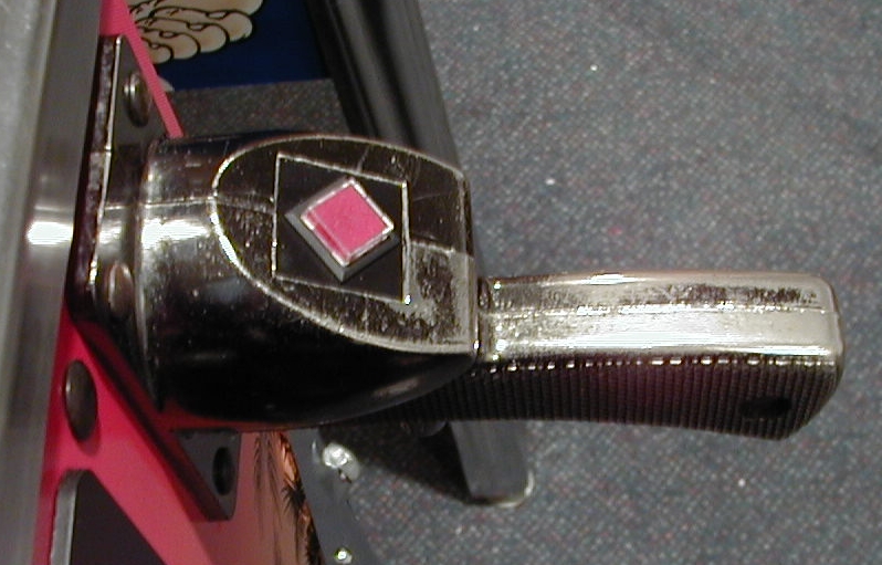
Illuminated Cast Button for Fish Tales PinballEarly models of the Fish Tales pinball machine used an illuminated pushbutton for the "cast" (ball launch) button; this feature was discontinued early in the production run, and a non-illuminated pushbutton was used instead. The original switch assembly specified in the Bill of Materials for the game was not available from any of the usual suppliers, so I cobbled up a replacement that looked similar to the original. Here's a picture of the end result:
Chris Bucci's Fish Tales web site had an image of the original style illuminated cast button. Chris was kind enough to supply the dimensions of the original button so I could find one that matched. This page contains the information you'll need to cobble up a similar item for your game. Total cost in parts is around $12; allow about two hours to make the modification. I've included several pictures to help you along. Feel free to e-mail me if you have questions: tony@dziedzic.us. Joseph "Tony" Dziedzic DISCLAIMERThis modification requires some electronics skills, and if done improperly may cause damage to your game. I cannot accept any responsibility for problems that arise from using this information. Parts List / Tools
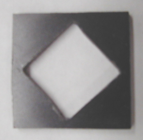
The electronic parts are available from Mouser Electronics; I've added Mouser part numbers in parentheses. As far as tools go, the only specialized tool is a T-25 security Torx bit. Sears sells a set of six security Torx bits (stock number 9-25702) for less than $10. You'll need a crimp tool for the Molex male terminals, a soldering iron, solder, a wire cutters, and a needle-nose pliers. A drill press, drill bits, and coping saw will be required to cut the mounting hole for the switch in the fender washer and black plastic. Step 1 - Remove the Handle AssemblyTurn the power off, remove the lock-down bar, the playfield glass, the balls, and raise the playfield to lean against the head. Disconnect the wire harness that leads to the handle assembly. Remove the four carriage bolts that secure the handle assembly to the cabinet (you'll need a 3/8-inch nut driver and a 3/8-inch box wrench). Step 2 - Disassemble the Handle AssemblyRemove the T-25 security Torx screws that join the two halves of the handle assembly. The existing push button switch assembly can be removed by pulling it from the slots inside the handle assembly. Keep the original switch assembly in case you want to remove the illuminated push button assembly some day. Step 3 - Fabricate the Switch Plate and BezelThis is probably the toughest step. You'll need to cut a 0.622-inch (5/8-inch is close enough) square hole in the fender washer and the piece of black plastic. If you have access to a 5/8-inch square hole punch you'll be able to make a really nice cutout with minimal effort. If you don't have the hole punch, and don't want to spend $20 to buy one, the alternative is to mark a 5/8-inch square centered on both pieces, drill pilot holes in the corners, and use a small coping saw with a metal-cutting blade to make the cutout. Note that the cutout in the plastic piece is 45 degrees offset from the sides of the plastic piece:
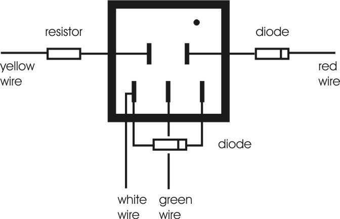
The switch has a small bezel surrounding the body that will hide some amount of sloppiness in the cutout. Spend a bit of extra time on the cutout in the plastic piece, since that's the one that will be most visible. Now test-fit the fender washer and plastic bezel in the two halves of the handle. If your fender washer is a little too thick you may have to use a bench grinder to thin out the surface of the washer near the edges, or flatten the edges a bit so the two halves of the handle fit together correctly. Be sure the fender washer and plastic bezel fit correctly and the cutout in each piece matches so you won't have problems when you complete the assembly. Step 4 - Wire the Push Button SwitchThe push button switch wiring isn't complicated, but be careful to connect the wires to the correct terminals. Use a low-wattage soldering iron when making the connections to the switch to avoid damage from over-heating. Use this diagram to locate where the various connections are made (this is a rear view of the switch):
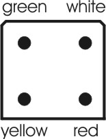
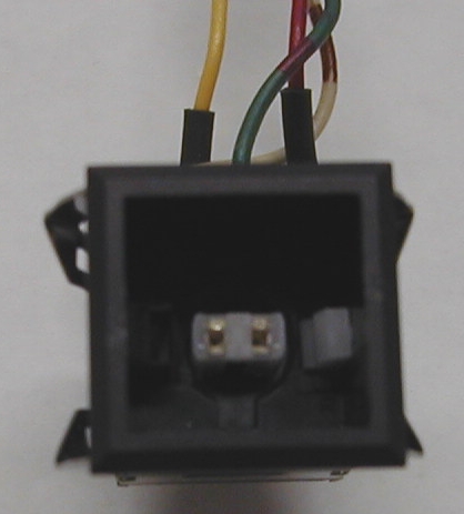
Step 5 - Wire the ConnectorCut the free ends of the four wires to the same length. Use a Molex crimp tool to connect the male terminal pins to the free ends of the wires. Insert the crimped wires into the REAR of the connector housing. The wires should be positioned as this FRONT VIEW of the connector housing indicates:
Double-check your switch and connector wiring before proceeding to the next step. Step 6 - Install the LED and Button CapPosition the LED so the flat side is aligned with the white actuating arm inside the switch, and insert the LED into the socket. Here's a picture of the inside of the switch showing the white actuating arm on the right side of the picture (sorry for the poor quality picture):
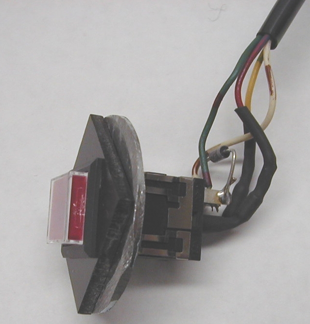
Look inside your switch's housing (with the white actuating arm positioned toward the right as in this picture) and you'll see a pair of molded ribs at the top inside edge of the housing, and a single molded rib at the bottom inside edge. The button cap also has a pair of molded ribs on one side, and a single molded rib on the other side. Insert the button cap into the housing such that the single rib on the button is facing up (i.e., so it aligns with the pair of ribs on the housing); the two tabs that project from the rear of the button are positioned toward the left and right. Push the cap down until it seats. You should be able to push the button down and feel the slight click as the switch engages; the button should spring back when you release it. Step 7 - Test the Button AssemblyWith the power off, connect the button assembly to the wiring harness of the pinball machine. Turn the power on, and use the test buttons to enter test mode. Advance to the Switch Edges test (T1), and verify that pushing the button registers as a closure of switch 31 (CAST). Leave the Switch Edges test, advance to the Single Lamps test (T8), and verify that the cast button flashes when you select lamp 87 (UNUSED). If everything worked as expected you can turn off the power, disconnect the button assembly from the wiring harness, and proceed to the next step. If either test failed, first check all your wiring connections on the switch and the Molex connector. If the Switch Edges test failed, verify the placement of the white and green wires and the diode across the bottom switch terminals. If the Single Lamps test failed, verify the placement of the red and yellow wires. It's possible you may have installed the LED incorrectly in the push button housing. You can pop the button cap off with a small screwdriver to verify the orientation of the LED. Step 8 - Insert the Button Assembly in the Plastic Bezel and Fender WasherBend the wires connected to the switch as shown in the following picture:
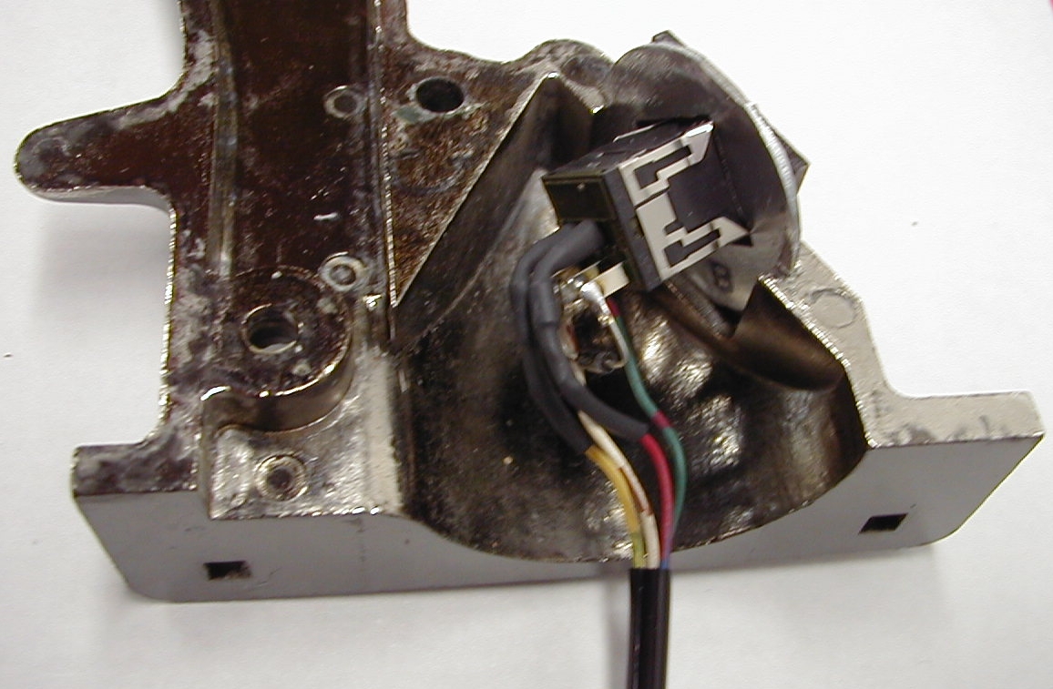
Place the plastic bezel on top of the fender washer and align the cutouts in both pieces. While holding these in position insert the Molex connector through the plastic bezel side, feed the wires through the pieces, and finally snap the push button switch into place. The small metal tabs on the sides of the switch will engage the bottom of the fender washer and hold the button firmly in place. Step 9 - Insert the Button Assembly in the Handle AssemblyAssuming you did a good job in step 3 you should be able to fit the button assembly into the two halves of the handle without any problems. The wires should lead out of the end of the handle that attaches to the cabinet as shown in this picture:
If the fit is too tight you'll have to make any necessary corrections before proceeding. Be sure none of the wires or the diode across the switch terminals are contacting the metal of the handle. Step 10 - Assemble the Handle AssemblyConnect the two halves of the handle using the original hardware. The Torx screws use a internal-tooth lock washer first followed by a flat washer; the blind nuts use just an internal-tooth lock washer. Step 11 - Replace the Handle AssemblyInsert the Molex connector through the opening in the front of the cabinet and replace the four carriage bolts that secure the handle assembly to the cabinet. Connect the Molex connector to the wiring harness of the pinball machine and position the connecting cable from the handle assembly so it doesn't interfere with closing the coin door. Replace the balls, the playfield glass, and the lock-down bar, and you're good to go! |