


|
|
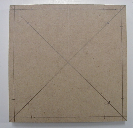
Plastic Display Panel Speaker ReplacementSafety tip: Be sure to disconnect the power to the game before performing any work! In order to replace the speakers the display panel must be removed from the game; you'll need to disconnect a few cables to do this. Before disconnecting any cable it's always a good idea to mark its position so the cable can be replaced properly. Make a mark on the pin 1 end of the connector and socket, and label the connector with the mating socket number. Hint: In the sections below you'll need to find the center of a square. It's very easy to do this by drawing diagonal lines from each corner of the square to the opposite corner using a straight edge and a pencil. The point where the two lines intersect to form an "X" is the center of the square. Safety tip: Wear eye protection when using power tools! A dust mask will come in handy for the operations that generate lots of dust. Remove the Display PanelRemove the translite panel assembly and set it in a safe location. Lift the display panel upward to free it from the upper mounting pivots, and then rotate the upper end of the panel forward. Slide the bottom end of the panel slightly backward until it clears the lower mounting pivots, and then pull the panel forward. Set the panel face down on a towel or other padding laid on the playfield glass. Follow the black and black-yellow wires from the left speaker into the back box to identify the specific connector on the A/V board, and then remove that connector from the board (it should be plugged in to J2). Now you can unravel the display panel speaker wiring harness from the back box wiring harnesses and cable clamps. Remove the power and data cables from the rear of the dot matrix display; don't forget to mark the pin 1 position of the power and data cables first! Remove the nut from the threaded stud on the left inside bottom corner of the back box, and then remove the green-yellow ground wire leading from the display panel. Now you can remove the display panel from the game. Disassemble the Display PanelSet the display panel on a padded work surface. Remove the clamp-on ferrite noise suppression choke from the speaker wiring harness (it snaps open for removal). Cut the wires from the speaker wiring harness where they attach to the left speaker. You can discard this harness, as we'll be replacing it with a new one. Also cut the two wires (black and black-yellow) that run from the left speaker to the right speaker. The black wire at the right speaker attaches to a solder lug; cut the wire at the lug. Remove the four Philips screws that mount the dot matrix display to its mounting studs. Remove the four flat washers and the insulating paper, and then lift the display straight off its mounting studs. Store the display face down on a towel or other padded material. Remove the four Philips screws that mount each speaker to its mounting plate, and then remove each speaker. Both speakers will have a green-yellow ground wire mounted under the lower mounting screw closest to the dot matrix display; save that for later re-installation. Don't throw the left (5-1/4 inch) speaker away yet; you may need to use it while fabricating a spacer for the new speakers. Keep the speaker mounting screws, too; you might be able to re-use those. Options for the Right SpeakerIf you were able to locate a 5-1/4 speaker mounting plate we'll replace the right mounting plate with that one; that allows us to use 5-1/4 coaxial speakers on both sides of the display panel. There are two options to consider if you can't locate an original style plastic mounting plate for the right side speaker: fabricating an adapter plate from MDF board and using a smaller 3-1/2 inch speaker, or fabricating a new mounting plate from MDF board (replacing the original right side one) and using a 5-1/4 inch speaker. Fabricating a new mounting plate is a bit more challenging than fabricating an adapter plate, but it does allow you to use 5-1/4 inch speakers on both sides of the display panel for more balanced sound. Proceed with the appropriate section below depending on whether you're replacing the right speaker mounting plate, using an adapter plate, or using a new mounting plate. Replace the Right Speaker Mounting PlateUse a spring hook or a small screwdriver to carefully pry off each of the push nuts that mount the right speaker mounting to the display panel. Don't damage the push nuts; you can re-use them to mount the replacement 5-1/4 inch speaker plate. Also be careful that you don't break the plastic mounting studs when prying. Lift the plate off the display panel and set it aside. Set the replacement mounting plate in place and use the old push nuts to fasten the plate in place. A 3/8 inch nut driver works well to press the push nuts onto the plastic studs. If you break the push nuts you can try to find replacements: Tinnerman PS250385 is a good match for the originals. You may need to fabricate a spacer for both speakers if the tweeter projects more than 5/16 inch beyond the front mounting plane. Continue on to the section to check if you need spacers. Fabricate an Adapter Plate for the Right SpeakerThe adapter plate is fabricated from 1/2 inch thick MDF board. The adapter plate will be 4-1/2 inches square, and will have a 2-3/4 inch diameter circular hole cut in the center. Here is a diagram of the adapter plate that we're going to fabricate:
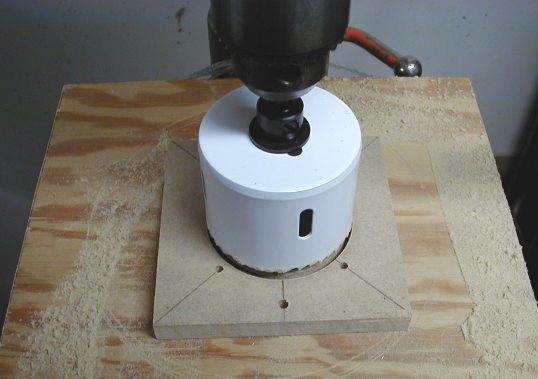
Cut a 1/2 inch thick piece of MDF board 4-1/2 inches square. A table saw is the best tool for this job; if you don't have a table saw you can use a portable circular saw. You can also have your local lumber dealer cut some pieces of MDF board to size for you. MDF board is relatively inexpensive, and it usually costs an extra quarter or fifty cents per cut for the lumber dealer to cut the MDF board to size. Draw diagonal lines from each corner of the board to its opposite corner; the point where the two lines intersect to form an "X" is the center of the board. Make marks on each diagonal line 1-19/32 inch from the center of the square (four marks total). The screws that mount the adapter plate to the speaker mounting plate will be installed at these points. Measure 2-1/4 inches from either the left or right edge of the board and make marks at the top and bottom of the board (two marks total). Draw a line from the top to the bottom of the board. Measure 3/8 inches from the top and 3/8 inches from the bottom of the board and make marks on the vertical line at those two points. The T-nuts that mount the speaker to the adapter plate will be installed at these points. If you're using a circle cutter adjust it to cut a 2-3/4 inch diameter circle. Be sure to securely clamp the MDF board to the table of the drill press before starting the drill press! Position the pilot bit where the two diagonal lines intersect and slowly advance the circle cutter until it has cut through the entire thickness of the board. Note that a 2-3/4 inch diameter hole saw is a also good way to make this cutout:
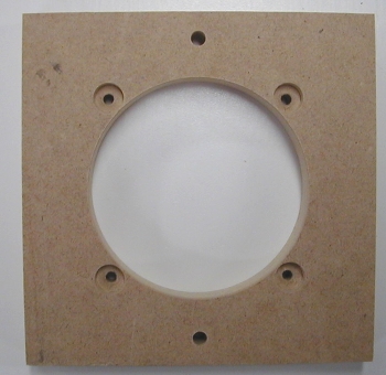
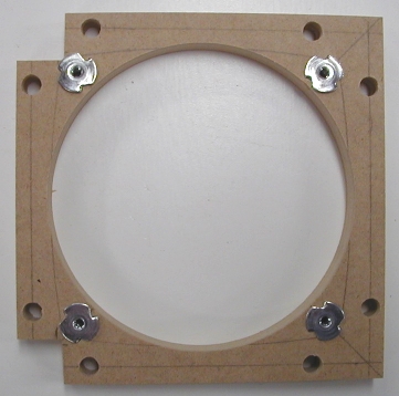
If you're using a jig or sabre saw, use a compass to mark a 2-3/4 inch diameter circle centered on the adapter plate. Drill a pilot hole for the saw blade just inside the circle, and then carefully cut along the line using the jig or sabre saw. Use a fine-toothed wood cutting blade so the cutout edges are smooth, and favor the inside edge of the line when cutting so the cutout isn't too large. Take your time and try to make the cutout as close to a perfect circle as you can. Drill 1/8 inch diameter holes at the four points marked on the two diagonal lines. Check these holes against the right speaker mounting plate; the holes should line up with the four speaker mounting studs. Once you're satisfied with the positioning of those four holes, use a Forstner drill bit to make a 3/8 inch diameter recess 1/4 inch deep at each of the four holes you just drilled. Be careful not to drill all the way through the adapter plate! If you don't have a drill press you can use a router with a flat bottom bit to make the recesses. The surface of the adapter plate with the recesses will be the "top" side. Drill 3/16 inch diameter holes at the two points marked on the vertical line. Use a hammer to seat #6 T-nuts in these two holes from the bottom side of the adapter plate (the bottom is the side without the recesses). The completed adapter plate should look like this; the T-nuts are on the back side:
You should paint the adapter plate with flat black paint so it blends with the display panel plastic. Continue on to the section to check if you need spacers. Fabricate a New Mounting Plate for the Right SpeakerThe mounting plate is fabricated from 1/2 inch thick MDF board. The mounting plate will be 5-3/4 inches square with 3/4 inch square notches cut out of two corners, and will have a 4-3/4 inch diameter circular hole cut in the center. Here is a diagram of the mounting plate that we're going to fabricate:
Cut a 1/2 inch thick piece of MDF board 5-3/4 inches square. A table saw is the best tool for this job; if you don't have a table saw you can use a portable circular saw. You can also have your local lumber dealer cut some pieces of MDF board to size for you. MDF board is relatively inexpensive, and it usually costs an extra quarter or fifty cents per cut for the lumber dealer to cut the MDF board to size. Draw diagonal lines from each corner of the board to its opposite corner; the point where the two lines intersect to form an "X" is the center of the board. Make marks on each diagonal line 2-3/4 inch from the center of the square (four marks total). The T-nuts that mount the speaker to the mounting plate will be installed at these points. Next we'll lay out lines for the 5/16 inch diameter holes that will accept the eight mounting studs that mount the mounting plate to the back side of the display panel. The placement of these mounting holes is critical, so take extra time to make exact measurements. Make a mark 1/4 inch in from each edge, and then draw a line parallel to each edge. Now measure 1-1/8 inch from each corner and make two marks on each line. When you're done you'll have made eight marks along the outside edges of the board. The board should look like this after all the layout lines have been drawn:
If you're using a circle cutter adjust it to cut a 4-3/4 inch diameter circle. Be sure to securely clamp the MDF board to the table of the drill press before starting the drill press! Position the pilot bit where the two diagonal lines intersect and slowly advance the circle cutter until it has cut through the entire thickness of the board. If you're using a jig or sabre saw, use a compass to mark a 4-3/4 inch diameter circle centered on the adapter plate. Drill a pilot hole for the saw blade just inside the circle, and then carefully cut along the line using the jig or sabre saw. Use a fine-toothed wood cutting blade so the cutout edges are smooth, and favor the inside edge of the line when cutting so the cutout isn't too large. Take your time and try to make the cutout as close to a perfect circle as you can. Cut two 3/4 inch square notches out of adjacent corners; these notches are required to provide clearance for the reinforcements on the sides of the display panel. Drill 5/16 inch diameter holes at the eights points on the lines parallel to the edges; use a brad-point drill bit so you can position the bit exactly at each mark. Drill 7/32 inch diameter holes at the four points marked on the diagonal lines; use a brad-point drill bit so you can position the bit exactly at each mark. Use a hammer to seat #8 T-nuts in these four holes from the bottom side of the mounting plate. The completed mounting plate should look like this when viewed from the bottom:
You should paint the mounting plate with flat black paint so it blends with the display panel plastic. Position the new mounting plate over the eight studs molded into the rear side of the display panel; the two notches on the new mounting plate should be positioned so they face the outside edge of the display panel, and the T-nuts should be on the bottom of the mounting plate (facing the plastic display panel).
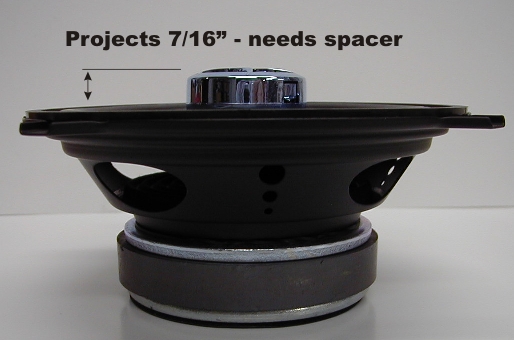
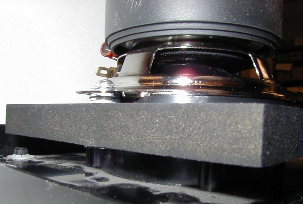
Mount the new mounting plate to the display panel using #6 x 5/8 inch pan head sheet metal screws; stick a #6 external tooth lock washer and a #6 flat washer under the head of each screw. At minimum install screws at the two top and two bottom holes on the mounting plate; you can install screws at the other four holes if you desire. Check if You Will Need SpacersGrab one of your 5-1/4 inch replacement speakers and set it on the magnet end so the tweeter is facing upward. Carefully lay a flat metal ruler or straight edge across the outside edge of the speaker next to the tweeter. Measure the distance from the bottom of the ruler or straight edge to the top surface of the tweeter. If this distance is more than 5/16 inch you'll need to fabricate a spacer for each side of the display panel that uses the original 5-1/4 inch speaker mounting plate. For example, the tweeter on this speaker projects 7/16 inch - it will need a spacer:
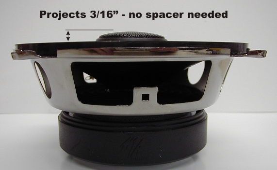
The tweeter on this speaker projects 3/16 inch - it will not need a spacer:
If you don't need spacers skip to the section on assembling the display panel. Fabricate SpacersThe spacers are fabricated from 1/4 or 3/8 inch thick MDF board; the thickness used depends on the front projection of the tweeter. Measure the projection of the tweeter (see above) and subtract 1/4 inch. If the remainder is less than 1/4 inch you can use 1/4 inch thick MDF board; if the remainder is more than 1/4 inch you'll need to use 3/8 inch thick MDF board. Here is a diagram of the spacer that we're going to fabricate:
Cut a piece of MDF board 6 inches square. A table saw is the best tool for this job; if you don't have a table saw you can use a portable circular saw. You can also have your local lumber dealer cut some pieces of MDF board to size for you. MDF board is relatively inexpensive, and it usually costs an extra quarter or fifty cents per cut for the lumber dealer to cut the MDF board to size. Draw diagonal lines from each corner of the board to its opposite corner; the point where the two lines intersect to form an "X" is the center of the board. Make marks on each diagonal line 2-3/4 inch from the center of the square (four marks total). The screws that mount the speaker to the display panel will pass through holes at these points. If you're using a circle cutter adjust it to cut a 4-3/4 inch diameter circle. Be sure to securely clamp the MDF board to the table of the drill press before starting the drill press! Position the pilot bit where the two diagonal lines intersect and slowly advance the circle cutter until it has cut through the entire thickness of the board. Stop as soon as the cutout section of MDF board starts to spin around with the circle cutter bit. Note: You may want to use a 1/4 inch brad-point drill bit to make a pilot hole before using the circle cutter; the pilot bit on the circle cutter is a standard drill bit that is a little tough to align exactly even with the center lines on the template. If you're using a jig or sabre saw, use a compass to mark a 4-3/4 inch diameter circle centered on the board. Drill a pilot hole for the saw blade just inside the circle, and then carefully cut along the line using the jig or sabre saw. Use a fine-toothed wood cutting blade so the cutout edges are smooth, and favor the inside edge of the line when cutting so the cutout isn't too large. Take your time and try to make the cutout as close to a perfect circle as you can. Drill 3/16 inch diameter holes at the four points marked on the two diagonal lines. If you can elongate the holes so they're oval-shaped along the diagonal lines that will give you an extra bit of adjustment room. Place the original 5-1/4 speaker on top of the spacer with the speaker mounting holes lined up with the holes in the spacer. Trace around the outline of the speaker with a pencil.
Remove the speaker and check that the edges of the lines you just traced are spaced evenly around the cutout in the spacer. Use a jig or sabre saw to carefully cut just to the outside of the pencil line. Here's what the spacer should look like when you're done drilling and cutting:
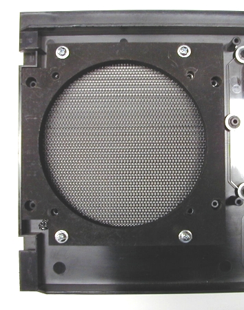
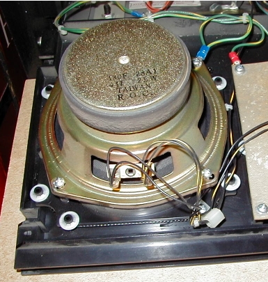
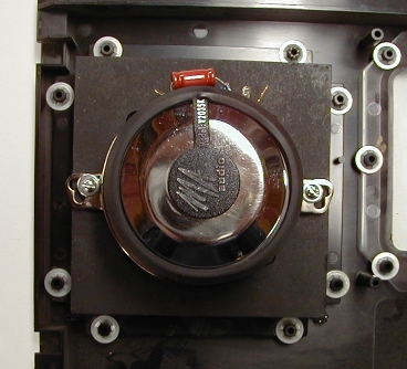
Place the spacer in position on the rear of the speaker mounting plate and verify that the holes you drilled line up with the mounting studs in the mounting plate. You may want to thread the four mounting screws originally used for the left speaker (the longer ones - #6 x 5/8 inch) through the holes in the spacer to be sure the holes will line up properly when you mount the speaker. After you've verified the fit of the spacer you should paint it with flat black paint so it blends with the display panel. The completed spacer should look like this when placed in position on the speaker mounting plate on the display panel: *EDITORIAL NOTE: Need new picture* Assemble the Display PanelYou will need to purchase some #6 pan head sheet metal screws of the correct length for mounting the left speaker (and the right speaker if you replaced the mounting plate for that speaker). The original sheet metal screws are "Type 25" (T-25); this type of screw has a thread-cutting notch at the thread end of the screw, and a somewhat flattened point. These screws do a great job cutting threads in plastic. If you can't find Type 25 screws regular sheet metal screws will work fine; just be sure to drive them slowly and stop if you feel any indication of the plastic stud cracking. Determine Speaker Mounting Screw LengthsMeasure the thickness of the speaker frame at any of the four mounting holes, add 1/4 inch to this measurement if you're using a spacer, and then add 1/4 inch to obtain the length of the new speaker mounting screws that you'll need. If possible, buy screws that are a multiple of 1/8 inch lengths (i.e., 5/8, 3/4, 7/8, 1-1/8, 1-1/4, etc.); this minimizes the chance that you'll crack the plastic mounting studs when driving the screws. If the measurement falls in the middle (such as 11/16 inches), round down to the next 1/8 inch multiple (5/8 inch in this case). Mount Replacement SpeakersWhen you mount the replacement speakers the terminal lugs should be positioned toward the top edge of the display panel. If the speaker has mounting lugs that extend from the sides of the speaker basket be sure to put some spacers between the lugs and the spacer or mounting plate; this way you won't distort the speaker basket when tightening the speaker mounting screws. Don't use excessive force when tightening the adapter plate or replacement speaker mounting screws; you may crack the plastic mounting studs. Each speaker has a green-yellow ground wire fastened under the lower mounting screw closest to the dot matrix display. The ground wire on the left speaker loops over to the lower left mounting screw of the dot matrix display. The free ends of the two ground wires exit the display panel in the area under the left speaker. Here's a picture of the original speaker setup:
Start by mounting the left speaker using #6 pan head sheet metal screws of the appropriate length, with #6 external tooth lock washers and #6 flat washers under the head of each screw. Next, mount the right speaker depending on the mounting option you chose. Using a Replacement Mounting Plate for the Right SpeakerMount the right speaker using #6 pan head sheet metal screws of the appropriate length. Continue on to final display panel assembly. Using an Adapter Plate for the Right SpeakerUse #6 x 5/8 inch pan head sheet metal screws to mount the adapter plate to the right speaker mounting plate. The adapter plate should be positioned so the two holes with T-nuts are located to the left and right of the speaker mounting plate as shown below:
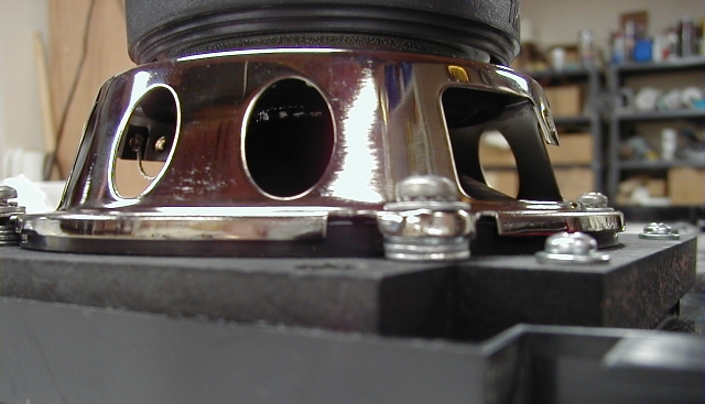
Mount the 3-1/2 inch coaxial speaker using two #6 x 3/4 inch round head machine screws; stick a #6 internal tooth lock washer and a #6 flat washer under the head of each screw. Depending on the particular model of speaker you use it may be necessary to add a few washers as spacers between the speaker mounting lugs and the surface of the adapter plate: three washers are about right for the MA Audio Y2035K. Nylon washers are easier to use as they're not magnetic and won't be attracted to the speaker magnet; metal washers work fine but require a bit of patience to install.
Here is the 3-1/2 inch speaker mounted to its adapter plate:
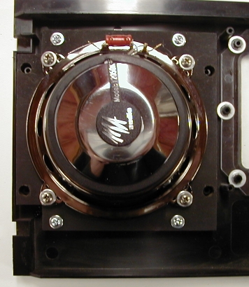
Continue on to final display panel assembly. Using a New Mounting Plate for the Right SpeakerMount the 5-1/4 inch coaxial speaker using four #8 x 3/4 inch round head machine screws; stick a #8 internal tooth lock washer and a #8 flat washer under the head of each screw (or use a SEMS fastener of the same length). Depending on the particular model of speaker you use it may be necessary to add a few washers as spacers between the speaker mounting lugs and the surface of the adapter plate: three washers are about right for the MA Audio Y3050K. Nylon washers are easier to use as they're not magnetic and won't be attracted to the speaker magnet; metal washers work fine but require a bit of patience to install.
Here is a top view of the 5-1/4 speaker mounted to its new mounting plate:
Final Display Panel AssemblyPlace the dot matrix display in position on its mounting studs. The connectors on the display are oriented toward the bottom edge of the display panel (facing away from the molded U-channel on the top edge of the panel). Replace the insulating paper, put a flat washer on each mounting screw, and then replace the screws that mount the display to the panel (the correct screws are #6 x 5/8 inch). Don't use excessive force when tightening the display mounting screws. We're done with the display panel for now; we'll wire it up after we're done with the cabinet speaker.
NEXT: cabinet speaker replacement HOME: WPC speaker replacement
Copyright © 2005 by Joseph A. Dziedzic. All rights reserved. |