


|
|
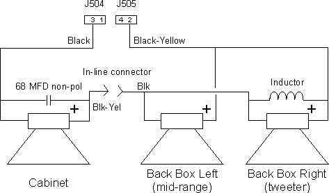
WPC-era Sound System InformationIn this section we'll look at the different sound systems used in WPC-era games, and the modifications we make to use replacement speakers.First Generation (pre-DCS)Early WPC games use an A-12738 sound card with a single LM1875 integrated circuit amplifier. The amplifier is rated to deliver a maximum of 25 watts of power to an 8 ohm load. This sound board was used on games from Funhouse through Twilight Zone (note that some early production Funhouse games used System 11 sound boards). The output connectors (J504 and J505) are wired in parallel, and are not labeled for specific connections; you can interchange the plugs to the two connectors without problems. Second Generation (DCS)The Digitally Compressed Sound (DCS) system was introduced with Indiana Jones. This system uses a pair of TDA2030A integrated circuit amplifiers in a two-channel arrangement. The sounds generated by the system are fed into a two-way crossover network with a crossover frequency of around 300 Hz. The low frequency output of the crossover network drives the cabinet speaker through one amplifier, while the high frequency output drives the back box speakers through a second amplifier. Each channel is rated to deliver a maximum of 18 watts of power to a 4 ohm load, and 12 watts of power to an 8 ohm load. The output connectors are labeled for back box or cabinet speakers; the plugs are keyed so they can only fit on the correct connector. Early versions (Indiana Jones through Who Dunnit) use a discrete A-16917 sound board, while later versions (through Cactus Canyon) use the combined A-20156 audio/visual board. Speaker ConnectionsWilliams used two different speakers in the back box: a midrange on the left side, and a tweeter on the right side. Pre-DCS Speaker Connections - Early GamesThe back box speakers are wired in parallel, with an inductor in parallel with the right speaker (the tweeter); the inductor serves to shunt low frequency sounds away from the back box speakers. Technically, the inductor forms a first-order low-pass filter. This configuration presents an effective impedance of around 4 ohms; the actual impedance will vary with frequency, but that can be ignored for this application. The cabinet speaker has a 68 MFD non-polarized capacitor in parallel with it; the capacitor serves to shunt high frequency sounds away from the cabinet speaker. Technically, the capacitor forms a first-order high-pass filter with a crossover frequency of 300 Hertz. The back box speaker combination is wired in series with the cabinet speaker. This results in an effective load impedance for the amplifier of around 12 ohms (depending on the frequency). The black lead from the cabinet speaker is connected to sound board connector J504 pin 3; the black-yellow lead from the cabinet speaker is connected to the black lead from the back box speakers via an in-line connector. The black-yellow lead from the back box speakers is connected to sound board connector J505 pin 2.
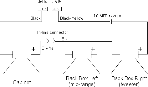
Pre-DCS Speaker Wiring - Early Games Note: Pins 1 & 2 and pins 3 & 4 are tied together on both J504 and J505. Games using this configuration (listed alphabetically): Pre-DCS Speaker Connections - Later GamesThe back box speakers are wired in parallel, with a 10 MFD non-polarized capacitor in series with the right speaker (the tweeter); the capacitor is used to block lower frequency sounds from being reproduced by the speaker. Technically, the capacitor forms a first-order high-pass filter with a crossover frequency of 4000 Hertz. This configuration presents an effective impedance of around 4 ohms; the actual impedance will vary with frequency, but that can be ignored for this application. In pre-DCS games the back box speaker combination is wired in series with the cabinet speaker. This results in an effective load impedance for the amplifier of around 6 to 8 ohms (depending on the frequency). The black lead from the cabinet speaker is connected to sound board connector J504 pin 3; the black-yellow lead from the cabinet speaker is connected to the black lead from the back box speakers via an in-line connector. The black-yellow lead from the back box speakers is connected to sound board connector J505 pin 2.
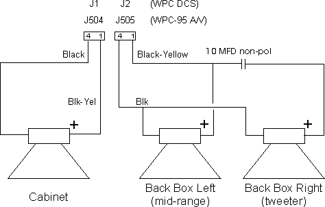
Pre-DCS Speaker Wiring - Later Games Note: Pins 1 & 2 and pins 3 & 4 are tied together on both J504 and J505. Games using this configuration (listed alphabetically): Note: Some Hurricane and Terminator 2 games have different wiring connections to J504 and J505; no in-line connector is used. Instead, the black wire from the cabinet speaker connects to J504 pin 3, and the black-yellow wire connects to J505 pin 2. The black wire from the back box speakers connects to J505 pin 4, and the black-yellow wire connects to J505 pin 1. DCS Speaker ConnectionsThe back box speakers are wired in parallel, with a 10 MFD non-polarized capacitor in series with the right speaker (the tweeter); the capacitor is used to block lower frequency sounds from being reproduced by the speaker. Technically, the capacitor forms a first-order high-pass filter with a crossover frequency of 4000 Hertz. This configuration presents an effective impedance of around 4 ohms; the actual impedance will vary with frequency, but that can be ignored for this application. In DCS games the back box speaker combination connects to one channel of the sound or A/V board via connector J2 (sound) or J505 (A/V). The cabinet speaker connects to the other channel of the sound or A/V board via connector J1 (sound) or J504 (A/V). In both cases the black wire connects to pin 4 of the connector and the black-yellow wire connects to pin 1.
DCS Speaker Wiring Note: A polarizing key is inserted in the pin 2 position of the back box speaker connector connected to J2 or J505. Games using this configuration (listed alphabetically): Replacement Speaker WiringThe new wiring scheme for both games is similar to the DCS speaker wiring in that each set of speakers is wired to a separate connector on the sound or A/V board. An L-pad is inserted into the back box speaker wiring to control the volume level of the back box speakers, and the back box speakers are wired in series instead of in parallel as in the original scheme. A crossover is inserted into the cabinet speaker wiring (the crossover is not needed for games using the DCS sound system).
New Speaker Wiring Note: A polarizing key is inserted in the pin 2 position of the back box speaker connector connected to J2 or J505 and in the pin 3 position of the cabinet speaker connector connected to J1 or J504.
HOME: WPC speaker replacement
Copyright © 2005 by Joseph A. Dziedzic. All rights reserved. |