


|
|
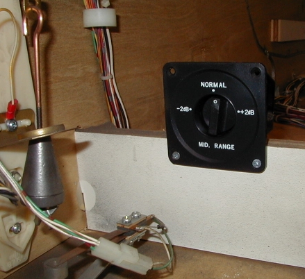
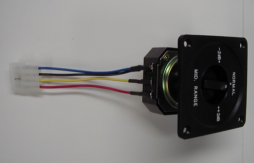
Wiring Replacement SpeakersWith the speakers installed in the game it's time to build the wiring harness that connects the components together. You'll need 18-gauge stranded wire in four colors (black, blue, red, and yellow), some Molex KK series connectors, and some 1/4 inch female quick disconnect terminals. Specific part numbers are listed in the Tools and Supplies section. Note: Williams wired the speaker system in a pre-DCS game in a somewhat odd fashion: the panel speaker combination is wired in series with the cabinet speaker. The set of three speakers is connected to the sound board via the J504 and J505 connectors. If you replace only the cabinet speaker or only the back box speakers, I would advise you to use the replacement wiring harness described below to simplify installation. See the section on single speaker set replacement considerations for more details. Determine Level Control Mounting LocationBefore you construct the wiring harness you need to decide where to mount the back box speaker level control. The control should be mounted someplace where it is easily accessible for adjustment. You won't need to adjust the control very often; the only time you might need to re-adjust it is if you were to change the game volume level significantly. My personal preference is to mount the control to the cabinet cross member immediately behind the cash box, toward the left side of the cabinet; this location provides easy access to the control when the coin door is open without interfering with anything on the rear of the coin door. This picture shows the Parts Express model 260-252 L-pad with an attached 260-270 face plate mounted to the cabinet cross member:
If you prefer, you can mount the level control on the inside of the coin door - assuming there is enough space on the door in your game. Mounting the level control to the coin door may not be possible if the coin door has a dollar bill stacker installed, if you have a 3-slot coin door, or if you have one of the older doors that can be configured for 1, 2, or 3 coin slots. Construct the Wiring HarnessNote: The wiring harness is built with extra wire length on each end to allow for adjustments in routing; the excess length will be trimmed when the harness is installed in the cabinet. The wiring harness consists of two sections; the first section connects the sound board to the back box speakers through the level control, while the second section connects the sound board to the cabinet speaker. These two sections are joined into a common harness as the following diagram illustrates:
You may wish to consult the schematic wiring diagram of the new sound system in the sound system info section for more details. If you plan to mount the level control on the cabinet cross member behind the cash box,
cut the following lengths of 18-gauge stranded wire:
Note: Add 12 inches to each wire length for WPC-95 games. If you plan to mount the level control on the inside of the coin door,
cut the following lengths of 18-gauge stranded wire:
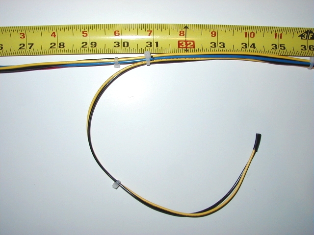
Note: Add 12 inches to each wire length for WPC-95 games. Use a small piece of masking or electrical tape to join one end of the four wires into a bundle. Secure this end of the bundle under a weighted object (a paint can works well) and stretch the wires out straight. Affix 4-inch cable ties to the wire bundle at points 6, 12, 18, 24, and 30 inches from the taped end of the wire bundle. If you're mounting the level control on the inside rear of the coin door affix additional cable ties at points 36, 42, 48, 54, 60, and 66 inches from the taped end. *EDITORIAL NOTE: Picture of taped end of harness with cable ties* If you're mounting the level control on the cabinet cross member measure 31 inches from the taped end of the wire bundle and make a mark on the yellow wire with a felt-tipped marker. If you're mounting the level control on the inside rear of the coin door measure 67 inches from the taped end of the wire bundle and make a mark on the yellow wire with a felt-tipped marker. Cut the following lengths of 18-gauge stranded wire:
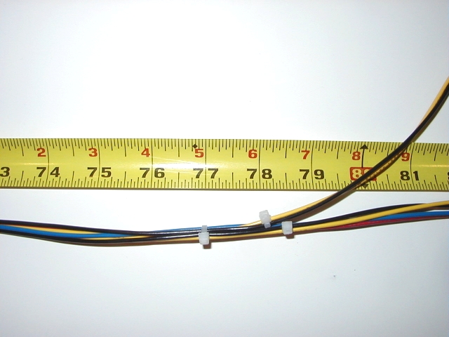
Use a small piece of masking or electrical tape to join one end of the two wires into a bundle. Secure this end of the bundle under a weighted object and stretch the wires out straight. Affix a 4-inch cable tie to the wire bundle at points 6 and 12 inches from the taped end of the wire bundle. Measure 17 inches from the taped end of the wire bundle and make a mark on the yellow wire with a felt-tipped marker. Position the two wire bundles side by side with the marked points next to each other, and the taped ends of the bundles facing the same direction. Affix a 4-inch cable tie at the marked point to join the two wire bundles together.
Continue to affix 4-inch cable ties every 6 inches from the marked point until you've reached a point 46 inches from the marked point. Separate the shorter black and yellow wires from the bundle here (these are the wires originally paired with the blue and red wires). If you're mounting the level control on the cabinet cross member this point is 77 inches from the taped end of the wire bundle. If you're mounting the level control on the coin door this point is 113 inches from the taped end of the wire bundle.
Affix 4-inch cable ties every 6 inches to the bundle of four longer wires (a black, a yellow, a red, and a blue) until you reach the end of that bundle. In the same manner affix 4-inch cable ties every 6 inches to the bundle of the shorter black and yellow wires until you reach the end of that bundle. Install the Wiring HarnessThe new wiring harness will lead from the cash box area near the front of the cabinet (or the coin door if you're mounting the level control on the inside of the coin door), along the left bottom side of the cabinet, through the corrugated plastic tube that contains the existing cabinet wiring harnesses, and into the back box. Connections will be made inside the cabinet to the level control, crossover, and cabinet speaker, and inside the back box to the sound or A/V board and to the back box speakers. At each connection point we'll install wire connectors for a factory appearance. Begin by placing the new wiring harness along the left inside edge of the cabinet next to the existing cabinet wiring harnesses. The previously marked point on the new wiring harness where the four- and two-wire bundles join should be placed at a point even with the rear of the cabinet speaker mounting block. The shorter end of the wiring harness should be positioned toward the front of the cabinet, and the longer end should be temporarily coiled up loosely in the rear of the cabinet.
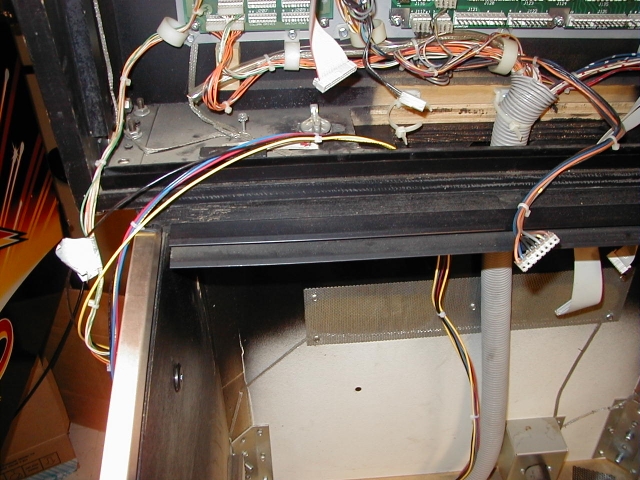
Fasten the new wiring harness to the existing cabinet wiring harnesses at a point even with the rear of the cabinet speaker mounting block using a 4-inch cable tie. Now take the longer end of the new wiring harness and insert it through the bottom of the opening in the cabinet pedestal where the back box mounts and through the bottom of the opening in the back box.
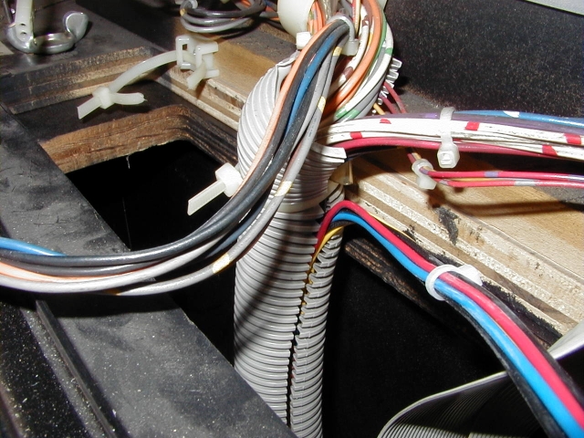
Note: This picture was taken with the playfield removed from the cabinet for easier access and better visibility. Route the new wiring harness alongside the existing cabinet wiring harnesses and fasten the new harness to the existing harnesses with 4-inch cable ties every 6 inches; start from the point even with the cabinet speaker mounting block and continue up to the area where the cabinet wiring harnesses enter the corrugated plastic tube (usually gray in color) that leads into the back box. Starting at the bottom end of the corrugated plastic tube use a finger to open the tube along the split end and stuff the new wiring harness into the tube. When you reach the point where the corrugated plastic tube is fastened to the rear of the back box bottom panel with a cable tie, cut the cable tie and remove it so you can stuff the new wiring harness inside the remaining length of the tube.
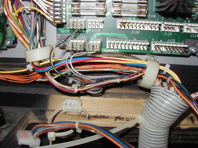
After you've stuffed the new wiring harness into the remaining length of the corrugated plastic tube, replace the cut cable tie with a new 7-inch one, and securely fasten the tube to the mounting block. Feed the new wiring harness through the cable clamp just to the left of the corrugated plastic tube. Route the new harness under the connections to the power driver board as shown in the picture.
Note: The playfield was removed from this game prior to installing the new wiring harness; consequently there are a number of headers on the circuit boards in the back box that do not have connectors attached in these pictures. For games with a metal speaker panel the paired black and yellow wires should be routed vertically through the cable clamps between the WPC CPU board and power driver board. For games with wooden or plastic display panels the paired black and yellow wires should be routed alongside the orange wires from the cabinet wiring harness that connect to the left side of the WPC CPU board. You can fasten the paired black and yellow wires to the existing cabinet harnesses near the cable clamp under the WPC CPU board with a 4-inch cable tie.
The loose ends of the black and yellow wires will be connected to the back box speakers later. The larger bundle of four wires should be routed vertically through the cable clamps between the WPC CPU board and the power driver board; the loose ends will be connected later to the sound or A/V board.
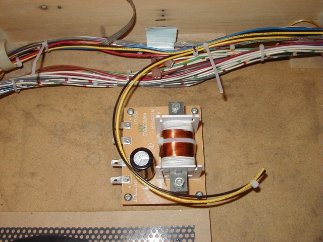
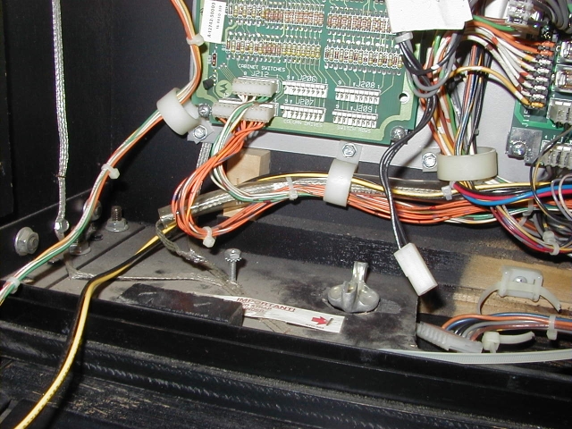
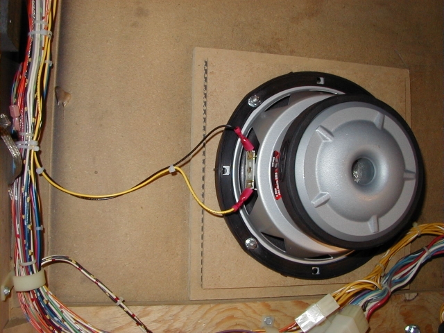
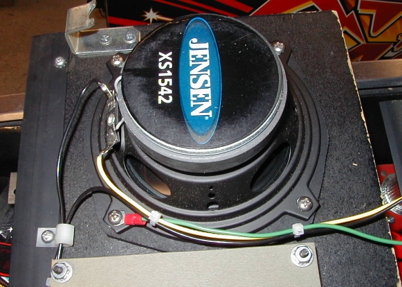
In this picture you can see the original cabinet speaker connector dangling next to the heat sink on the power driver board; the in-line connector from the cabinet speaker cable is visible on the right side of the picture (this is a pre-DCS sound system game). Later you will fasten these wires to one of the existing wiring harnesses running in the space between the power driver and sound (or A/V) boards. Connect the Cabinet Speaker and CrossoverTake the free ends of the black and black-yellow wires from the old cabinet speaker wiring and fasten them to the existing cabinet wiring harnesses using some 4-inch cable ties. Not Using a Crossover or InductorIf you are not using a crossover or inductor, simply connect the black and yellow wires that split from the new wiring harness in the area of the speaker mounting block directly to the speaker terminals; the black wire is connected to the "-" terminal and the yellow wire is connected to the "+" terminal.
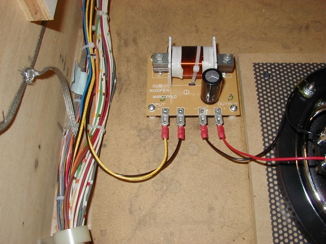
If the speaker has male quick connect terminals strip 1/8 inch from the free ends of the black and yellow wires and crimp female quick disconnects onto the stripped end of each wire. Use quick disconnects that match the width of the speaker terminals (usually 1/4 or 3/16 inch), and that are sized to fit 18-gauge wire. Carefully slide the quick disconnects onto the speaker terminals; the black wire is connected to the "-" terminal and the yellow wire is connected to the "+" terminal. If the speaker doesn't have quick connect terminals strip 1/4 inch from the free ends of the black and yellow wires. Connect the free ends of the black and yellow wires to the speaker terminals; black to the "-" terminal and yellow to the "+" terminal. If the speaker terminals are not of the spring-loaded quick connect style, solder the black and yellow wires to the terminals. Using a CrossoverIf you are using a crossover, form loops in the black and yellow wires that split from the new wiring harness in the area of the speaker mounting block; hold the wires in position on the crossover terminals and cut the wires to length. Strip 1/8 inch from the ends of each wire and crimp a 1/4 inch female quick disconnect onto each wire; use a disconnect sized to fit 18-gauge wire. Carefully slide the quick disconnects onto the crossover "INPUT" terminals; the black wire is connected to the "-" terminal and the yellow wire is connected to the "+" terminal.
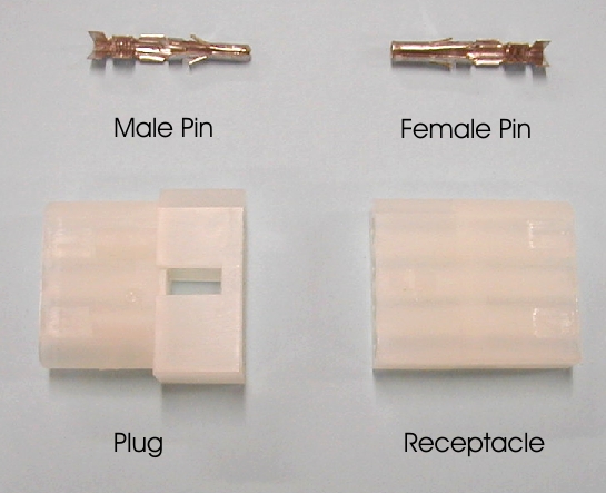
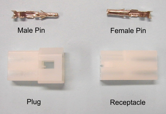
Cut appropriate lengths of black and red 18-gauge stranded wire to lead from the crossover terminals to the speaker terminals. Strip 1/8 inch from one end of each wire and crimp a 1/4 inch female quick disconnect onto one end of each wire; use a disconnect sized to fit 18-gauge wire. Carefully slide the quick disconnects onto the crossover "OUTPUT" terminals; the black wire is connected to the "-" terminal and the red wire is connected to the "+" terminal. If the speaker has male quick connect terminals strip 1/8 inch from the free ends of the black and red wires and crimp female quick disconnects onto the stripped end of each wire. Use quick disconnects that match the width of the speaker terminals (usually 1/4 or 3/16 inch), and that are sized to fit 18-gauge wire. Carefully slide the quick disconnects onto the speaker terminals; the black wire is connected to the "-" terminal and the red wire is connected to the "+" terminal. If the speaker doesn't have quick connect terminals strip 1/4 inch from the free ends of the black and red wires. Connect the free ends of the black and red wires to the speaker terminals; black to the "-" terminal and red to the "+" terminal. If the speaker terminals are not of the spring-loaded quick connect style, solder the black and red wires to the terminals. Using an InductorIf you are using an inductor it should be wired in series with the cabinet speaker. Connect the black wire to the "-" terminal of the speaker. Connect either wire from the inductor to the yellow wire (solder and insulate the connection, or use a small wire nut), and then connect the other wire from the inductor to the "+" terminal of the speaker. Depending on the specific inductor that you used and the mounting location, you may need to splice some extra wire length on to the inductor wire that is connected to the "+" terminal of the speaker. *PICTURE NEEDED* Connect the Level ControlWe'll use Molex KK series inline connectors to connect the level control to the new sound system wiring harness. Here is a picture of the two types of connectors we'll use and the two types of pins used in these connectors:
The positions in the Molex plug and receptacle are numbered beginning at the pointed end (the top of the connectors in this picture). If you look very closely at the rear of the connectors (the ends facing away from the center of the picture) you can just barely make out the numbers molded into the rear surface of the connector. Wiring the Level ControlThe new wiring harness will accommodate either an L-pad or a rheostat; only the connections to the control differ. Proceed with the appropriate section below depending on the type of level control you're using. Using an L-pad as a Level ControlCut 6 inch lengths of black, yellow, blue, and red 18-gauge stranded wire. Strip 1/4 inch from one end of each wire. Solder the black and blue wires to the common terminal of the L-pad; this terminal is usually marked with a "1". Solder the yellow wire to the speaker terminal of the L-pad; this terminal is usually marked with a "2". Solder the red wire to the amplifier terminal of the L-pad; this terminal is usually marked with a "3". Cut three 1/2 inch lengths of 3/16 inch diameter heat shrink tubing. Slide the heat shrink tubing over the free ends of the wires and onto the L-pad terminals. Heat the tubing with a hair dryer or heat gun until the tubing has shrunk tightly around the terminal and wire. Strip 1/8 inch from the free ends of the four wires. Crimp a Molex 02-09-2118 male terminal pin onto the stripped end of each wire. Insert the four terminal pins into the rear of a Molex 03-09-2042 4-circuit plug. The red wire is in position 1, the yellow wire is in position 2, the black wire is in position 3, and the blue wire is in position 4 (nearest the flat side of the plug). When you're done the L-pad should look like this:
Note: This picture shows the Parts Express model 269-112 L-pad; while other models will differ somewhat in appearance, the connections are basically the same. Using a Rheostat as a Level ControlCut 6 inch lengths of yellow and red 18-gauge stranded wire and strip 1/4 inch from one end of each wire. Solder the yellow wire to the terminal in line with the control shaft, then solder the red wire to either terminal at the ends of the arc-shaped ceramic former on which the rheostat wires are wound. Note that some rheostats may only have a single terminal on the arc-shaped former. Cut two 1/2 inch lengths of 3/16 inch diameter heat shrink tubing. Slide the heat shrink tubing over the free ends of the wires and onto the rheostat terminals. Heat the tubing with a hair dryer or heat gun until the tubing has shrunk tightly around the terminal and wire. Cut a 5 inch length of black 18-gauge stranded wire and strip 1/8 inch from each end. Crimp a Molex 02-09-2118 male terminal pin onto each stripped end of the wire. Insert the two terminal pins into the rear of a Molex 03-09-2042 4-circuit plug in positions 3 and 4 (nearest the flat side of the plug). Strip 1/8 inch from the free ends of the red and yellow wires. Crimp a Molex 02-09-2118 male terminal pin onto the stripped end of each wire. Insert the terminal pin with the red wire into position 1, and insert the terminal pin with the yellow wire into position 2. *PICTURE* Mounting and Connecting the ControlNow we'll mount the level control in the location you previously selected. The control and the wiring harness will be connected using Molex KK series in-line connectors. Control Mounted to the Cabinet Cross MemberMount the control to the cabinet cross member immediately behind the cash box area, centered about six inches from the left side of the cabinet. If you're using the Parts Express model 269-112 L-pad you can use a pair of #4 x 1/2 inch flat head wood screws. You'll need to use a flat washer between the rear of the control and the cross member as the faceplate of the L-pad is depressed at the mounting screw locations. If you're using a different model of control you'll need to fabricate an appropriate mounting bracket. Position the taped end of the new wiring harness in the general vicinity of the cabinet cross member immediately behind the cash box area and remove the tape from the end of the new wiring harness. Check the length of the free ends; you'll need about six inches for connection to the level control from the point where the wiring harness passes under the control (see the picture below). Strip 1/8 inch from the free ends of the four wires (black, yellow, blue, and red). Crimp a Molex 02-09-1119 female terminal pin onto the stripped end of each wire. Insert the four terminal pins into the rear of a Molex 03-09-1042 4-circuit receptacle; the red wire is in position 1, the yellow wire is in position 2, the black wire is in position 3, and the blue wire is in position 4 (nearest the flat side of the receptacle). The rear of the receptacle has a flat and a rounded side; the end with the flat and triangular side plugs into the mating connector.
Connect the level control connector and the wiring harness connector together; double-check that the wire colors line up across both connectors. Tuck the wires neatly behind the cabinet cross member. Finish by securing the new wiring harness to the existing cabinet wiring harnesses with 4-inch cable ties every 6 inches from the area alongside the cabinet speaker mounting block toward the front of the cabinet. Stop at the area where the cabinet wiring harnesses take a vertical turn by the cross member behind the cash box area. Control Mounted on the Inside of the Coin DoorFabricate an appropriate mounting bracket and mount the level control on the inside of the coin door. Route the taped end of the new wiring harness through the nylon cable clamps on the left side of the cabinet next to the cabinet cross member, up and over the pendulum tilt assembly, and through the cable clamp next to the coin door hinge. Check the length of the free ends; you'll need about six inches for connection to the level control from the point where the wiring harness passes under the control. Be sure to leave enough slack so you can open the coin door fully! *PICTURE* Strip 1/8 inch from the free ends of the four wires (black, yellow, blue, and red). Crimp a Molex 02-09-1119 female terminal pin onto the stripped end of each wire. Insert the four terminal pins into the rear of a Molex 03-09-1042 4-circuit receptacle. The red wire is in position 1, the yellow wire is in position 2, the black wire is in position 3, and the blue wire is in position 4 (nearest the flat side of the receptacle). The rear of the receptacle has a flat and a rounded side; the end with the flat and triangular side plugs into the mating connector. Connect the level control connector and the wiring harness connector together, and tuck the wires neatly behind the cabinet cross member. Finish by securing the new wiring harness to the existing cabinet wiring harnesses with 4-inch cable ties every 6 inches from the area alongside the cabinet speaker mounting block toward the front of the cabinet. Stop at the area where the coin door frame is mounted to the front of the cabinet. Fasten the new wiring harness to the existing wiring harness that runs from the interface board to the coin door. Connect the Back Box SpeakersWe'll use Molex KK series inline connectors to connect the back box speakers to the new sound system wiring harness. Here is a picture of the two types of connectors we'll use and the two types of pins used in these connectors:
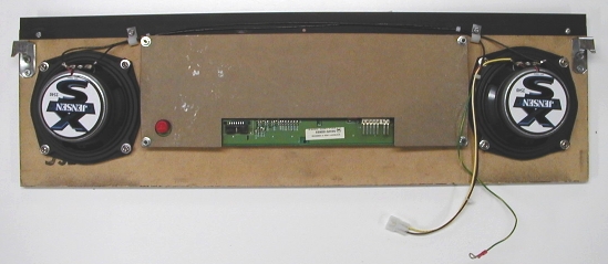
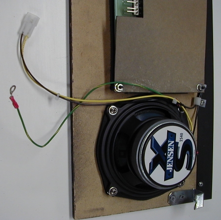
The positions in the Molex plug and receptacle are numbered beginning at the pointed end (the top of the connectors in this picture). If you look very closely at the rear of the connectors (the ends facing away from the center of the picture) you can just barely make out the numbers molded into the rear surface of the connector. Speaker Terminal Polarity MarkingsSpeaker terminals are usually marked to indicate the polarity; there are several common markings. There may be a "-" or "+" marked next to or on the terminal; there may be a dot of red paint to denote the "+" terminal or a dot of black paint to denote the "-" terminal; or the terminals may be of different widths. In the latter case the wider one (1/4 inch) is the "+" terminal, and the narrower one (3/16 inch) is the "-" terminal. Wooden or Plastic Display PanelNote: In the text below "left" and "right" refer to the speaker positions as seen with the display panel installed in the game. Cut a length of yellow 18-gauge stranded wire 12 inches long and strip 1/4 inch from one end. Solder the stripped end of the yellow wire to the "+" terminal of the left speaker. (You can use crimp-on female quick disconnect terminals instead of soldering if you'd prefer; in that case only strip 1/8 inch from the wire end.) Cut a length of black 18-gauge stranded wire 24 inches long and strip 1/4 inch from each end. Solder one end of the wire to the "-" terminal of the left speaker, and solder the other end of the wire to the "+" terminal of the right speaker. Cut a length of black 18-gauge stranded wire 32 inches long and strip 1/4 inch from one end. Solder the stripped end of the wire to the "-" terminal of the right speaker. Route the wires from the right speaker through the cable clamps along the top edge of the display panel. Use a few 4-inch cable ties on the two black wires where they are routed through the cable clamps on the top of the display panel.
Use some 4-inch cable ties to fasten the black and yellow wires to the ground wire attached to the left speaker.
Trim the free ends of the black and yellow wires to the same length and strip 1/8 inch from the ends. Crimp a Molex 02-09-2118 male terminal pin onto the stripped end of each wire. Insert the two terminal pins into the rear of a Molex 03-09-2022 2-circuit plug with the yellow wire in position 1 and the black wire in position 2 (nearest the flat side of the plug).
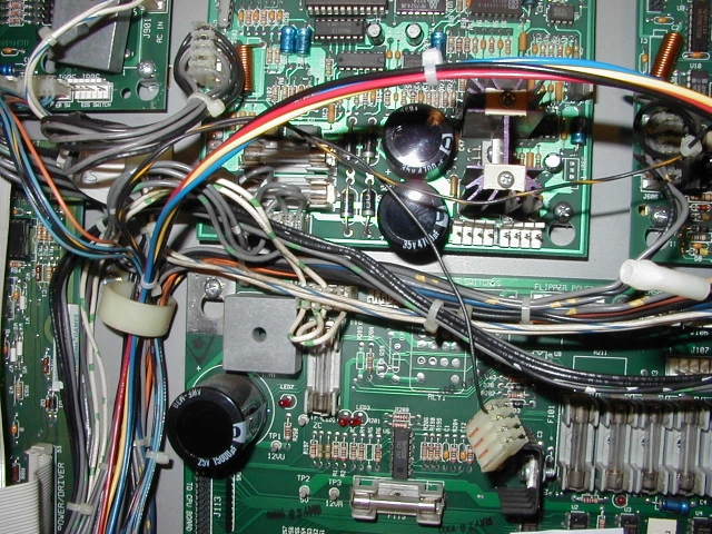
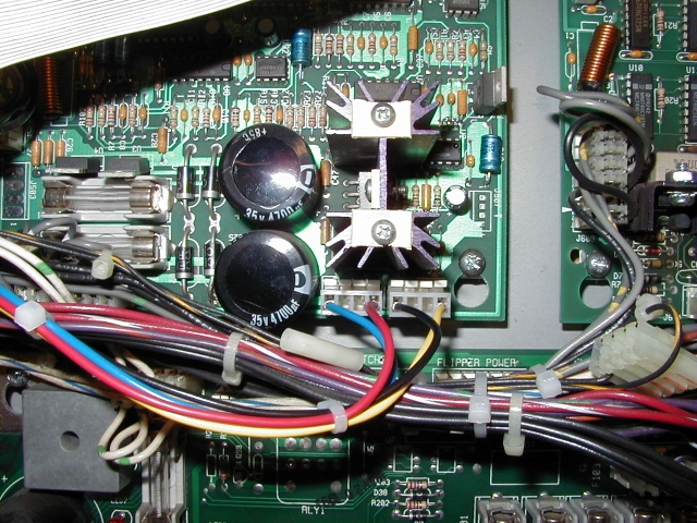
Strip 1/8 inch from the free ends of the black and yellow wires leading from under the WPC CPU board in the back box. Crimp a Molex 02-09-1119 female terminal pin onto the stripped end of each wire. Insert the two terminal pins into the rear of a Molex 03-09-1022 2-circuit receptacle with the yellow wire in position 1 and the black wire in position 2 (nearest the flat side of the receptacle). The rear of the plug has a flat and a rounded side; the front end with the flat and triangular side plugs into the mating connector. Lay a towel or other padding on top of the cabinet side rails immediately in front of the back box, and set the display panel on top of the padding. Hold the display panel in place and connect the green/yellow wire to the ground stud in the bottom left corner of the back box; tighten the nut securely. Connect the plug from the new wiring harness to the receptacle leading from the display panel speakers. Re-connect the power and data cables to the display panel; be sure to align the pin 1 end of the cables to match the corresponding socket. If there is a feature lamp panel mounted on the display panel re-connect the cable to that board too. Replace the display panel in its normal position in the back box. Metal Speaker PanelNote: In the text below "left" and "right" refer to the speaker positions as seen with the speaker panel installed in the game. Cut a length of yellow 18-gauge stranded wire 36 inches long and strip 1/4 inch from one end. Solder the stripped end of the yellow wire to the "+" terminal of the left speaker. (You can use crimp-on female quick disconnect terminals instead of soldering if you'd prefer; in that case only strip 1/8 inch from the wire end.) Cut a length of black 18-gauge stranded wire 22 inches long and strip 1/4 inch from each end. Solder one end of the wire to the "-" terminal of the left speaker, and solder the other end of the wire to the "+" terminal of the right speaker. Cut a length of black 18-gauge stranded wire 58 inches long and strip 1/4 inch from one end. Solder the stripped end of the wire to the "-" terminal of the right speaker. Route the wires from the right speaker through the cable clamps along the top edge of the speaker panel. Trim the free ends of the black and yellow wires to the same length and strip 1/8 inch from the ends. Crimp a Molex 02-09-2118 male terminal pin onto the stripped end of each wire. Insert the two terminal pins into the rear of a Molex 03-09-2022 2-circuit plug with the yellow wire in position 1 and the black wire in position 2 (nearest the flat on the side of the plug). *PICTURE* Strip 1/8 inch from the free ends of the black and yellow wires leading between the WPC CPU and power driver boards in the back box. Crimp a Molex 02-09-1119 female terminal pin onto the stripped end of each wire. Insert the two terminal pins into the rear of a Molex 03-09-1022 2-circuit receptacle with the the yellow wire in position 1 and the black wire in position 2 (nearest the flat on the side of the receptacle). The rear of the plug has a flat and a rounded side; the front end with the flat and triangular side plugs into the mating connector. Hold the metal speaker panel in position in front of the top area of the back box; be careful, as the panel is quite heavy, and you don't want it to come crashing down on the playfield glass! Feed the new speaker wiring harness and the green ground wire into the opening in the top front of the back box and replace the metal panel in its place. Fasten the lower edge of the panel in place with the four tamper-resistant Torx T-20 screws you removed earlier. Release the setup latch on the rear of the back box and fold the back box onto the playfield rails; place a towel or other padding between the back box and the cabinet. Next, replace the four tamper-resistant Torx T-20 screws that fasten the metal speaker panel to the top of the back box. Raise the back box to the upright position and fasten the setup latch on the back of the back box, and then replace the two bolts that secure the back box to the cabinet. Replace the hex-head sheet metal screw (with the ring terminal of the green ground wire under the screw head) in position in the top right corner of the metal backing panel in the back box. Route the wiring harness from the back box speakers to the left of the sound board and to the area between the WPC CPU and power driver boards. Connect the plug from the new wiring harness to the receptacle leading from the back box speakers. Connect the Wiring Harness to the Sound or A/V BoardRemove the cabinet speaker cable connector from the sound or A/V board. If you have a WPC-95 game remove the clamp-on ferrite noise suppression choke from the speaker wiring harness (it snaps open for removal). Route the free end of the new wiring harness in the back box between the power driver board and the sound or A/V board. Check the length and trim if necessary; leave enough wire length to form a gentle loop where the wires connect to the sound or A/V board. Strip 1/8 inch from the free ends of the four wires (black, yellow, blue, and red). Crimp a Molex 08-52-0113 "Trifurcon" terminal pin onto the stripped end of each wire. Hold a Molex 09-50-3041 connector housing with the locking ramps facing away from you and the open ends of the connector housing facing toward you; the locking ramps should be on the top side of the housing. Insert the terminal pin with the black wire in the left-most position of the housing, then insert the terminal pin with the yellow wire in the right-most position of the housing. Be sure to align the small locking tang on the flat side of the terminal with the groove in the connector housing. *PICTURE OF HOUSING* Hold a Molex 09-50-3041 connector housing with the locking ramps facing away from you and the open ends of the connector housing facing toward you; the locking ramps should be on the top side of the housing. Insert the terminal pin with the blue wire in the left-most position of the housing, then insert the terminal pin with the red wire in the right-most position of the housing. If you have a game with the DCS sound board or A/V board you may wish to install polarizing keys in the connector housings so you can't plug either connector onto the wrong header. Do not use the polarizing keys on games with pre-DCS sound boards! The keys are inserted into the end of the connector housing closest to the locking ramp. Insert a Molex 15-04-0219 polarizing key into the position next to the black wire on the connector with the black and yellow wires, then insert a Molex 15-04-0219 polarizing key into the position next to the red wire on the connector with the blue and red wires. If you have a WPC-95 game replace the clamp-on ferrite noise suppression chokes around the back box and cabinet speaker wires. Each pair of wires should be wrapped once around the choke. Plug the connector with the black and yellow wires onto header J504 on the pre-DCS sound or A/V board, or header J1 on the DCS sound board. Plug the connector with the blue and red wires onto header J505 on the pre-DCS sound or A/V board, or header J2 on the DCS sound board. Here is a view of the connectors installed on a pre-DCS sound board:
Be aware that the positions of the connectors on a DCS sound board are reversed from this picture; i.e., the connector with the black and yellow wires would be on the left. The connectors are in the same positions as this picture on an A/V board. Fasten the loose ends of the old cabinet speaker connections to one of the existing wiring harnesses in the back box that run between the power driver and sound or A/V board. Sound Quality TipSome WPC-95 games may have scratchy or tinny sound due a design flaw in early production versions of the A/V board. This can often be resolved by removing two capacitors (C47 and C51) on the A/V board. Check Clay's WPC Repair Guide section on Sound Problems for details; scroll down to the section titled "Static and Scratchy/Tinny Sound on Early WPC-95 Games".
NEXT: finishing up HOME: WPC speaker replacement
Copyright © 2005 by Joseph A. Dziedzic. All rights reserved. |